We still get invited to work with new clients who have a small fleet of mobile cranes and a permanent crane operator crew. Typically the operators did not attend a union apprenticeship program, and has simply gained knowledge about cranes from an in-house process, sometimes rather hand-me-down. ITI is glad to work with organizations like this to conduct mobile crane operator training since they have a desire to upgrade their employees’ skill and knowledge levels and have chosen our company to get them “on-track”. Certainly we would make sure they are compliant with the state OSHA, federal OSHA requirements and the ASME B30.5 Mobile Crane standards. Blended with the training would be informational blocks concerning the manufacturer’s requirements and “best practices” for the cranes in their fleet. Concerning mobile crane load charts we would want their folks to realize:
- Initially, the gross load rating charts are based on a combination of crane components in place, such as; counterweights by number and location on the crane, jibs stowed/erected, number of boom section (lattice inserts), hooks blocks and the like.
- Secondly, the gross load rating charts are affected by the crane “footprint” such as; on- tires stationary, on-tires pick/carry, outriggers extended 0/50/100%, and crawlers retracted/extended to name a few.
- On hydraulic cranes the capacity can vary greatly based on which telescoping sections are deployed. Special lift capacity columns are often available to the operator which indicates “manual or power-pinned fly” and a whole new crop of cranes provide capacity information based on multiple sections extended 46%-50% out to 100% so a designated column may read; base, 46%, 46%, 100%, 100%. The more sophisticated the boom configuration, the more adept the operator needs to be to ensure proper agreement between the on-board LMI dash-mounted computer and the actual crane setup.
- The crane’s load chart generally references the “reeving” (parts-of-line) capacity in conjunction with the wire rope as specified by the crane manufacturer. If the hoist rope specification changes, the lifting capacity can be affected, generally downward. During a project in Nigeria, I worked with a few cranes that could accept different sizes of hoist rope for the main hoist. They site opted to use the smaller diameter wire rope for the crane and unwittingly reduced the maximum lift capacity of the crane by 1/3.
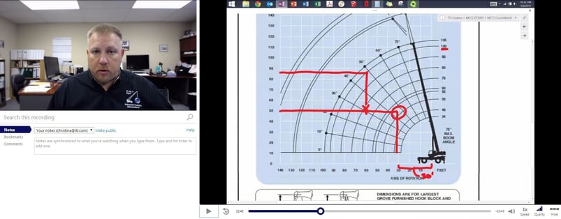
- The crane’s range diagram is generally a part of the load chart decaling, or in the capacity chart notebook. This is an excellent perspective for an operator to determine the crane’s reach up and over obstructions.
- Ensure that the gross capacity load chart and all accommodating chart and diagrams reference the specific crane’s serial number anytime capacity can be affected. The crane was built with a set of parameters in mind which revolve around the criteria being applied in a planned manner. Any shortcuts or unapproved replacements can jeopardize the crane’s ability to perform as planned. A substitute component that is not “up-to-snuff” with the original crane designer’s specifications can lead to disaster.
As the 2018 OSHA Crane Rule Deadline approaches, ITI has expanded its training solutions to ensure that all operators are prepared for certification. Offerings include:
For more information visit https://www.iti.com/courses/cranes or call 800.727.6355 today.


COMMENTS